|
 [25
June 2020] My mum came across
one of these "Brian the Robot"
toys originally from
Confused.com. [25
June 2020] My mum came across
one of these "Brian the Robot"
toys originally from
Confused.com.
It's pretty crappy (thanks all
the same mum!), but I was
wondering if I could do
something with it.
Before testing it I looked on
Youtube and saw that it
simply plays a cycle of audio
snippets when the button on the
front is pressed. It's supposed
to move along when pulled back
(like a toy car) but mine is
clearly broken in this regard.
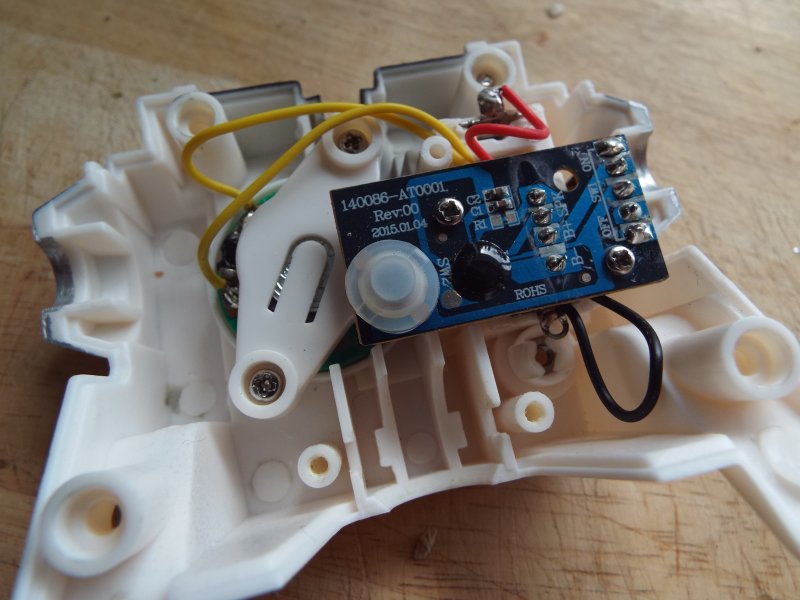
It has the name "BRI4N" on the
back, in the style of a vehicle
number plate, which is why I was
given it.
It
takes 3 x LR44 button-cell
batteries so I ordered some to
test the thing... It works.
I
had seen some Youtube videos of
people 'circuit-bending' such
electronics but it seems this
toy's circuitry is too basic.
For now, I have put Brian the
Robot to use on the
Page
Not Found page.
[08
August 2020] I recently acquired
a 'Science Fair' [read more on
the
Electronics page] and began
reading the included manual and
learned about the
'potentiometer'. I remembered
this from the circuit-bending
videos I'd watched on Youtube,
and figured out how I might use
it on Brian.
This
video I watched illustrated the
basics; I needed to remove a
resistor and swap it for a
variable one.
Sadly Brian didn't have a
resistor, but what he did have
was a pair of blank pads on his
small circuit board labelled
'R'. I suspected this stood for
Resistor and meant it was an
optional surface mountable
component for the board. Two
nearby components were labelled
each as 'C', I assumed for
capacitors.
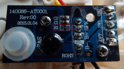
According to the
Wikipedia page on SMT
(Surface-mount technology),
which is what this is,
Capacitors are usually blank, as
can be seen above and below,
whereas typically a Resistor of
this type would have a
three-digit number on.
When
I looked closely I could just
about see that the two resistor
pads were joined together by a
trace on the board. I confirmed
this with my circuit tester. I
then cut through the trace and
tested again; the continuity was
now broken between the two pads.
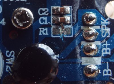
I
then soldered wires to each of
the pads and tested again. If I
joined the wires then Brian
worked as normal. I then rigged
Brian up to my newly acquired
Science Fair, well its
potentiometer at least, to see
what would happen...
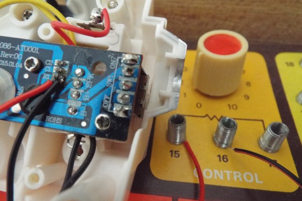
It
only gave me the ability to
control Brian's speaker volume,
and not do any funky
circuit-bending [I can see that
the R1 leads immediately to SPK
(speaker)]. Oh well. At least he
doesn't have to be so shouty
now. [perhaps I can 'bend' the
sound of his voice in other
ways?] Back to the
Page
Not Found page he goes for
now.
[Back
to Top]
|