|
 [23
August 2020] I recently found myself
on Noel's Retro Lab Youtube channel
and, having a slight interest in
retro computers, I found myself
watching a video where Noel
diagnoses and repairs a noise
distortion problem on a ZX Spectrum
+3 (I used to have one of these) [link
to video]. [23
August 2020] I recently found myself
on Noel's Retro Lab Youtube channel
and, having a slight interest in
retro computers, I found myself
watching a video where Noel
diagnoses and repairs a noise
distortion problem on a ZX Spectrum
+3 (I used to have one of these) [link
to video].
His
process was easy to follow and he
did an excellent job of not only
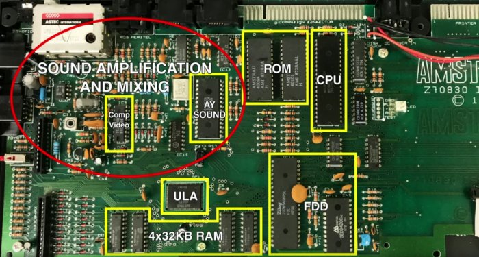
showing the problem area on the
board (although it looked fine), but
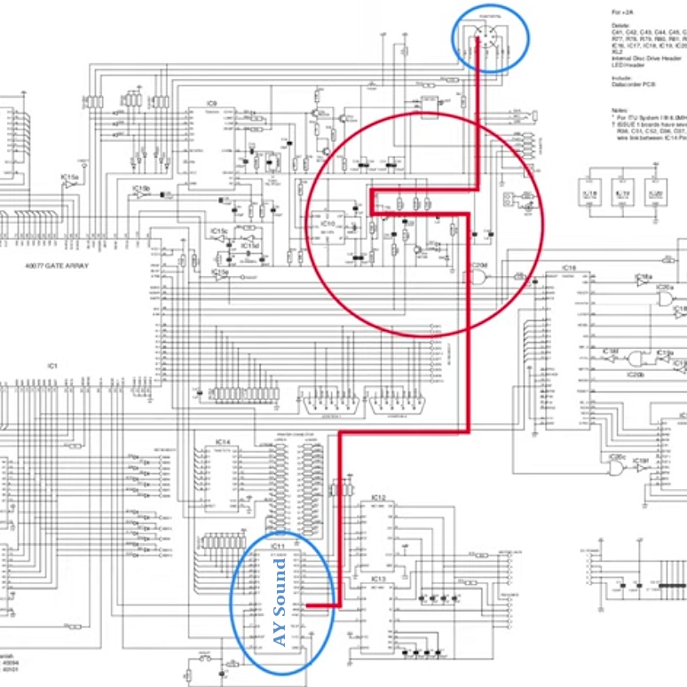
he compared it to the circuit
diagram, and then isolated the audio
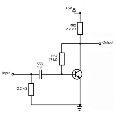
amplifier section and illustrated
that part on its own.
Here are those
three stages:


Circuit diagram showing the path of
the audio output from the Sound
Chip,
through the amplifier circuitry, and
out through the video port.

Simplified ZX Spectrum +3
Amplification Circuit
Noel
further explained that this is a
Single Stage Amplifier. I can see
the similarities between this and my
previous Science Fair amplifier
project which also featured a single
transistor (unlike the first more
complex one which used three). There
is also a noticeable absence of a
transformer.
"A transformer is an electrical
apparatus designed to convert
alternating current from one voltage
to another. It can be designed to
"step up" or "step down" voltages
and works on the magnetic induction
principle." - Google
From
this I assume this conversion is
carried out prior to the circuitry
illustrated above. The common
ground, as i guess it would be
termed, is also omitted from this
simple diagram.
- - - -
-
[25
August 2020]
Today I
turned to a book I have called
Starting Electronics by Keith
Brindley. It says:
[We] can still only guess at what
[electricity] is. It's actually
impossible to see electricity: we
can only see what it does...
This
statement reminded me about the
topic of gravity in the book I
recently re-read called Einstein's
universe.
[Back
to Top]
|