|
|
|
|
Mac Pro 2006... |
[Page last
reviewed June
2026] |
|
|
 I
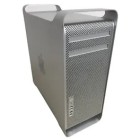
acquired my Mac Pro 2006 1,1 (A1186) in
November 2024 (IRRC). Despite being
nearly twenty years old, it
appeared to be in remarkably good
condition and was fully functional
when I received it. The only
obvious issues were some minor
cosmetic damage to the case,
likely caused by the machine's
considerable weight (over 25kg),
and a faulty optical drive door
that would no longer retract
properly. I
acquired my Mac Pro 2006 1,1 (A1186) in
November 2024 (IRRC). Despite being
nearly twenty years old, it
appeared to be in remarkably good
condition and was fully functional
when I received it. The only
obvious issues were some minor
cosmetic damage to the case,
likely caused by the machine's
considerable weight (over 25kg),
and a faulty optical drive door
that would no longer retract
properly.
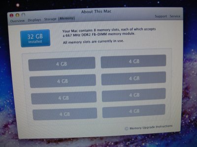
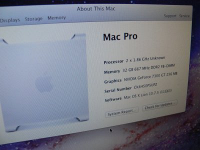
The
system came equipped with an
impressive 32 GB of RAM and all
four hard drive bays populated,
providing a total of 4TB of
storage. As I had no particular
use for the original hard drives,
I sold them and cloned the main
system disk to an SSD instead
(you'll need a suitable 2.5" to
3.5" drive adapter for this).
My
intention was to repurpose the
machine as a Linux workstation and
run Einstein@Home on its dual Xeon
processors. Unfortunately, the
project quickly took an unexpected
turn.
I was
unable to boot a Linux installer
from USB, so I installed an SSD
containing an existing Ubuntu
installation from another
computer. Ubuntu booted
successfully, but the original
Nvidia GeForce 7300 GT displayed
severe graphical corruption,
either due to driver issues or
poor compatibility with the
desktop environment. While
experimenting with alternative
Linux distributions and desktop
environments, the system suddenly
crashed.
After
the crash, the Mac Pro would no
longer start. Pressing the power
button produced no startup chime
and the machine failed to boot.
Prior to this, I had occasionally
needed to reseat the RAM riser
cards to restore normal operation,
so memory-related issues were
among my first suspicions.
My
initial troubleshooting steps
included checking the motherboard
diagnostic LEDs. When the power
button was pressed, only the
Standby (Trickle Power) and Power
Good LEDs illuminated; none of the
CPU- or temperature-related
indicators were active. I also
reset the CMOS and replaced the
PRAM battery, but none of this
made any difference.
At
this point it was clear that
further investigation would
require dismantling the machine.
What initially appeared to be a
straightforward fault would
eventually lead to a much more
extensive repair than I had
anticipated.
|
|
|
|
Dismantling:
[Disclaimer: The information
presented on this page is based
on my experience,
I am not responsible for what
you do to your system.]
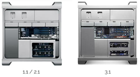
Before proceeding, it is worth
noting that there are at least
two internal variants of the
2006 Mac Pro. Mine is the
version shown on the left below,
identifiable by the arrangement
of the RAM riser slots.
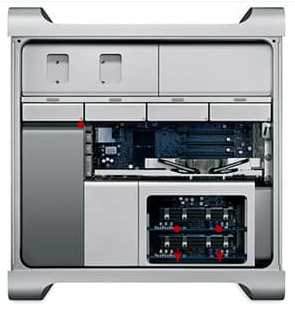
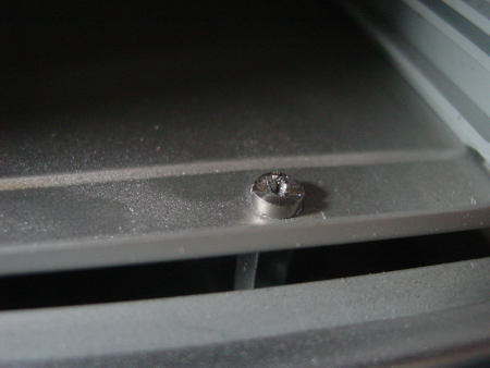
To
gain full access to the lower
are of the system that house the
RAM and CPUs, the RAM cards can
be pulled out, then the five
screws shown in the image below
must be removed to unfasten the
housing itself. Four of these
become accessible once the RAM
riser cards have been removed,
and removing the graphics card
beforehand makes the process
considerably easier.
|
|
|

Finding this page useful? |
|
|
The
two lower screws caused me
particular difficulty. Research
suggested that this is a fairly
common problem, and in my case
both screws appeared to have
been installed with
thread-locking compound. The
heads stripped almost
immediately when I attempted to
remove them.
To
overcome this, I carefully cut
slots into the screw heads using
a rotary tool, taking care to
vacuum away any metal particles
as I worked. Once modified, the
screws could be removed with a
flat-bladed screwdriver. The
standoffs beneath the screws may
come out as well. This part of
the job required patience, but
eventually the screws were freed
without causing any damage.
With
the screws removed, the RAM
housing becomes loose and the
internal shrouds can be
separated. The front intake fan
section is particularly awkward,
but can be carefully worked free
once its retaining screw has
been removed. The fan assembly
connects directly to the
motherboard via an integrated
multi-pin connector, so it
effectively disconnects as the
shroud is removed.
At
this stage, it is possible to
access and clean the front fan
and the leading edges of the CPU
heatsinks without fully
dismantling the system. Given
the amount of dust present in
this area, this alone is highly
recommended for any second-hand
unit.
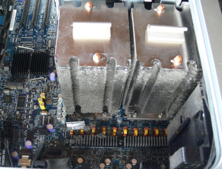
Shroud and front intake fan
removed to reveal dust.
To
continue further, the CPU
heatsinks must be removed. This
requires a long driver
(approximately 20 cm) to reach
the eight mounting screws.
Although a 3 mm hex driver is
specified, I found that a T15
Torx driver was more practical
and widely available.
Each
heatsink includes a temperature
sensor attached near its base,
which must be disconnected from
the motherboard before removal.
It is also important to note the
orientation of each heatsink, as
the rubber pads differ between
positions.
Once
removed, I proceeded with CPU
replacement and reinstalled the
cleaned heatsinks. On first
power-on, the system chimed and
appeared to function normally.
However, this success was
short-lived.
After shutting the machine down
and reconnecting the SSD, it
failed to boot again. The fans
immediately ramped to maximum
speed and there was no startup
chime. At this point, the fault
remained unresolved, and both
CPU and power delivery issues
were still under consideration.
Given the uncertainty, I began
investigating the mainboard as a
possible cause. A replacement
board was sourced as a
diagnostic step, since sourcing
another power supply at
reasonable cost was not
practical at that stage.
When
it arrived, the condition of the
packaging did little to inspire
confidence. The board had been
shipped with minimal protection,
and could be felt through the
outer wrapping.
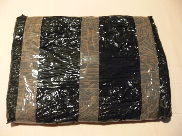
Some
people seem to lack any
understanding about how computer
parts such as mainboards,
graphics cards, or RAM should be
handled, or how best to package
them. Typically such things are
static-sensitive, but not even
putting an item like this in a
box... come on.
Despite my doubts, I proceeded with
installation. The Mac Pro logic board replacement is a relatively
involved process due to the number of tightly packed connectors
and limited clearance within the chassis, but the swap was
completed successfully.
The original board was tested once
more before removal and briefly appeared to function, further
adding to the uncertainty. Based on this, I suspected an
intermittent fault possibly related to power delivery.
 The
replacement board initially failed to produce a startup chime,
reinforcing the suspicion that the underlying issue was not
resolved. However, when tested again the following day, the system
did start successfully. The
replacement board initially failed to produce a startup chime,
reinforcing the suspicion that the underlying issue was not
resolved. However, when tested again the following day, the system
did start successfully.
At this point the
behaviour became inconsistent.
The machine would occasionally
boot and operate normally, but
stability was not reliable.
After further testing with the
Linux installation and workload
stress, the system eventually
failed again in a similar
manner.
This pattern strongly suggested
an upstream power instability
rather than a single permanently
failed component. By this stage,
the power supply had become the
primary suspect once again.
|
|
 |
|
Delving into the Power Supply:
With
the processor theory and
suspected mainboard issues
becoming increasingly unlikely,
my attention returned to the
power supply.
Finding a replacement unit
proved difficult. Apple produced
multiple variants for the Mac
Pro 1,1, including differences
in connector layout and internal
design. Some versions appear to
use a single high-capacity 12 V
rail, while others, like mine,
use multiple 12 V rails (in this
case six). The multi-rail design
is less appealing for potential
upgrades, as load distribution
is not clearly documented and
there is a greater risk of
unintentionally overloading
individual rails.
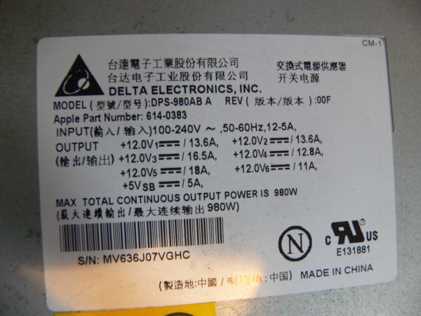
As
is often the case with
multi-rail PSUs, it is not
obvious how the internal
components are mapped. In this
unit, six rails appear to be
present but only four output
connectors are exposed, with no
clear labelling of their
distribution.
Before proceeding, a word of
caution: power supplies can
contain potentially dangerous
voltages even after they have
been disconnected from the
mains. Do not attempt to
dismantle or repair one unless
you understand the associated
risks and know how to work
safely.
The Mac Pro PSU is secured within
the chassis and connected via four cable assemblies. Once these
are disconnected, the unit can be removed and split into two
sections.
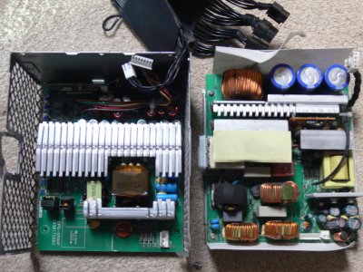
From
my understanding, the right half
deals with the AC
input and the left half
provides the DC outputs.
My previous experience
repairing older electronics often involved replacing electrolytic
capacitors. While not a precise diagnostic method, degraded
capacitors are a common failure point in ageing power supplies,
particularly on output rails where thermal and electrical stress
is highest. Dust accumulation can further accelerate this ageing
process by reducing cooling efficiency and increasing operating
temperatures.
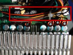
In this case, I
identified a cluster of six capacitors on the 12 V output side
that appeared to be the most likely starting point. None showed
obvious signs of failure, but visual inspection alone is not
always reliable.
My usual method for
replacing through-hole capacitors is slightly unorthodox. Rather
than desoldering the entire component in one operation, I first
remove the capacitor body, leaving the legs in place. These can
then be desoldered individually after applying flux from the
reverse side of the board. I find this approach easier when
dealing with large, tightly mounted components.
On this occasion, the
repair initially went poorly. As each leg was removed, solder
reflowed into the holes, making it difficult to seat the
replacement components cleanly. After several attempts and
increasing frustration, I set the project aside.
Several months later,
after gaining more experience with similar repairs, I returned to
the PSU.
This time I changed
approach. I shortened the replacement capacitor leads to
approximately 5 mm and applied a generous amount of thick flux.
Each capacitor was held in position while heat was applied from
the underside of the board, gently working the joints until the
softened solder allowed the leads to pass through and the
components to seat correctly.
Once all six
capacitors were replaced, I reflowed each joint with a small
amount of fresh solder, trimmed the excess leads, and cleaned the
board thoroughly with isopropyl alcohol.
Given the difficulty
of the original repair, I had little confidence it would succeed.
I expected either immediate failure or no response at all from the
system.
Instead, the Mac Pro
powered on.
A moment later it
chimed.
Shortly afterwards, it
booted into the operating system.
Most importantly, it
remained stable under operation.
At that point, it was
clear that neither the processors nor the mainboard were the root
cause. The replacement CPUs remained installed, but the fault had
almost certainly originated in the power supply. Whether the
capacitors I replaced were definitively faulty is difficult to
prove without further testing, but the repair restored the machine
from a non-booting state to a fully functional system.
|
|
|
|
Installing Linux:
The next step was getting Linux
running reliably on the Mac Pro 1,1.
This model presents a well-known
challenge: although it uses 64-bit Xeon processors, it is
constrained by a 32-bit EFI firmware implementation. As a result,
many modern Linux installers will not boot directly from USB in
the usual way.
I attempted to work around this by
trying a range of Linux distributions, including both newer and
older releases, but none of them successfully booted from USB on
this machine.
In the end, I took a more indirect
approach. I installed an SSD in another Intel-based system and
used that machine to perform the initial Linux installation. I
chose an older Ubuntu release that was compatible with the Mac
Pro’s graphics hardware, as later versions and some alternative
distributions proved unreliable when moved across.
Once installed, the SSD was
transferred back into the Mac Pro. Although this approach felt
somewhat like a workaround, it proved to be the most practical way
of getting a working system in place.
With Linux finally running, I
turned my attention to installing BOINC and setting up
Einstein@Home. The system initially struggled with outdated
software repositories, but once those issues were resolved I was
able to install BOINC and begin testing workloads on the original
dual-core Xeon processors.
At this stage my plan was to
measure system stability and power consumption before moving on to
the quad-core Xeon upgrade I had already purchased. The goal was
to compare performance and efficiency between the original and
upgraded CPU configurations under sustained computational load.
I installed Psensor, a simple Linux
hardware monitoring tool used to track system temperatures in real
time. This allowed me to monitor CPU and system thermals under
load while running BOINC workloads, giving a clearer picture of
how the ageing cooling system and Xeon processors were coping
during sustained computation.
|
|
|
|
Swapping the Xeons:
Swapping the Xeons
marked the point where I could finally push the system a bit
further.
The original
processors in my system were a pair of dual-core 2.0GHz Xeons, and
after researching compatible LGA771 processors, I purchased a pair
of quad-core Xeon E5320 CPUs. They were inexpensive, readily
available, and offered twice the core count of the originals,
albeit at a slightly lower clock speed of 1.86GHz.
With the heatsinks
already familiar to me from the earlier dismantling work, the
installation process was relatively straightforward. With the
plastic heatsink cover removed, and the heatsinnk towers
themselves lifted out, the old processors were carefully replaced
with the quad-core Xeons, and fresh thermal compound was applied
before reassembly. Everything was reinstalled with particular
attention to the heatsink screwes, being sure to not over tighten
them.
Once reassembled, the
system powered on without hesitation.
This time, however, I
could immediately push it further.
With all eight cores
now available from the upgraded CPUs, I loaded the system with
Einstein@Home workloads through BOINC and monitored it under
sustained load. Psensor was used throughout to track CPU
temperatures and confirm that the cooling system was still keeping
everything within safe limits, as I expected it would, given that
systems could have been purchased from Apple with this setup.
Despite the earlier
instability and failed boot attempts, the system proved to be
completely stable under load. Both the operating system and BOINC
ran without interruption.
At full load, the
system drew approximately 345W from the wall, a useful benchmark
for understanding its power consumption under sustained
computational work.
What had begun as a
machine that refused to boot had now become a stable 8-core
workstation running continuous scientific workloads.
|
|
|
|
Upgrading the GPU:
With
the system now stable under
sustained load, my attention
turned to another potential
upgrade; the graphics card.
The
original Nvidia GeForce 7300 GT
is extremely limited by modern
standards, and I had considered
replacing it with something more
capable. However, this
immediately raised questions
around power delivery. Many
modern GPUs require additional
6-pin or 8-pin PCIe power
connectors, and it was not
initially clear how safely this
could be achieved within the
constraints of the Mac Pro 1,1
power design.
The
system does provide additional
power outputs beyond the
standard drive connectors, but
Apple’s internal distribution of
power is not as straightforward
as a modern PC power supply.
While the PSU is often described
as having multiple 12V rails,
the way these are routed through
the logic board makes it
difficult to determine how load
is actually distributed between
components such as the CPUs,
storage devices, and expansion
hardware.
I
briefly considered using the
available Molex power connectors
from the optical drive bay or
tapping into the SATA power
lines for the hard drive
backplane. However, these are
also integrated into the
system’s internal power
distribution path, and I was
wary of placing additional load
on circuits that were already
supporting the dual Xeon
processors and other components.
On
closer inspection, I discovered
that Apple had in fact provided
a more appropriate solution: two
dedicated mini 6-pin power
connectors intended specifically
for graphics cards. These offer
a far cleaner and more direct
way of powering a GPU upgrade
without modifying the internal
power distribution.
With
this in mind, I decided to
proceed with a modest and
realistic upgrade target. After
checking compatibility and
expected power draw, I settled
on aiming for a mid-range card
such as an Nvidia GTX 1060,
which represents a significant
improvement over the original
hardware without pushing the
system into unrealistic power
requirements.
I
have since ordered the necessary
mini 6-pin adapter cable and
will revisit the GPU upgrade
once I'm ready to try it out.
|
|
|
|