|
[17
August 2020] I assembled one of the
other amplifiers. I think there are
four in total; the first one is
project 2 (seen on the
previous page), but there
are three others in the dedicated
Amplifiers section (61, 62, 63). 2
was quite complex compared to 61 as
it includes the switch and Control
knob/variable resistor, whereas 61
is on as soon as you apply power.
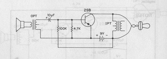
Circuit
diagram for project 61.
Both use
the 9V battery. I tested 2's power
prior to disassembly and setting up
61 and found it to have a peak
output voltage of 4V with the
Control turned up to 9 (you couldn't
turn it beyond that without the
sound breaking up). I was able to
measure this with both my dedicated
circuit tester and the included
Meter. 61 instead could only be
tested with my circuit tester which
reported 1.5V output.
-
The
variable resistor (Control) in the
first amplifier is labelled as a 50K
resistor and it connects via three
points. I'm wondering how I can
connect this in a similar fashion to
project 61 to give me some control.
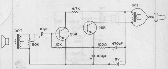
(I have looked ahead to the next two
amplifier projects and see 63 has
the Control resistor across the
microphone.
-
Strangely, in these diagrams, the
input, labelled IPT looks like the
earpiece used for output, and the
output, labelled OPT looks like a
loudspeaker which is a loudspeaker
but is used for input! That had me
confused for a while and thinking
the diagrams were labelled wrong.
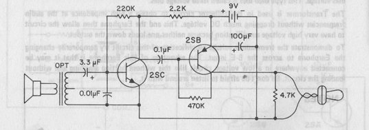
Here are
the next two projects in the
Amplifier series:
[Continue]
[Back
to Top]
|